

Description
MAX7219 digital tube display module control module cascade finished product
Significantly save your microcontroller’s resources. No timer scans are required, freeing the microcontroller for more tasks! Data only needs to be transferred once when the display is updated!
MAX7219 Digital Display Controller
The MAX7219 is an integrated serial I/O common-cathode display driver that connects microprocessors to 8-digit 7-segment LED displays, bar graph displays, or 64 individual LEDs. It includes an on-chip B-type BCD encoder, multiplexer circuitry, segment drivers, and an 8×8 static RAM to store individual data. A single external register sets the current for each LED segment.
A convenient four-wire serial interface connects to all common microprocessors. Individual data points are addressable, eliminating the need to rewrite the entire display when updating. The MAX7219 also allows the user to encode or unencode individual data points.
The device includes a 150μA low-power shutdown mode, analog and digital brightness controls, a scan limit register allowing the user to display 1-8 digits, and a detection mode that illuminates all LEDs.
Only three IO ports are needed to drive an 8-bit digital display! The display is flicker-free! Cascading is supported!
Copper studs are used at the four corners of the PCB to effectively prevent short circuits and other accidents!
The digital display is a 0.36-inch 4-digit common-cathode digital display.
This module is compatible with 5V/3.3V microcontrollers (51, AVR, STM32, etc.).
Wiring Instructions (Using the provided program as an example, you can connect to any IO port by simply modifying the port definition in the program):
VCC → 5V
GND → GND
DIN → P00
CS → P01
CLK → P02
Notes:
1. Do not connect VCC and GND in reverse to avoid damaging the chip.
2. Port P0 of the 51 microcontroller requires a pull-up resistor. If your microcontroller does not have a pull-up resistor, you can connect the data line to another port.


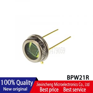 BPW21R BPW21 565nm CAN-2 Silicon Photodiode New
Reviews
There are no reviews yet.