Description
- Brand Name: Your Cee
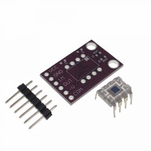
- Accessory Type: IV Conversion Amplifier
- Origin: Mainland China
- Compatible With: APDavalanche photodiode
- Power supply voltage: 12v
Special attention:
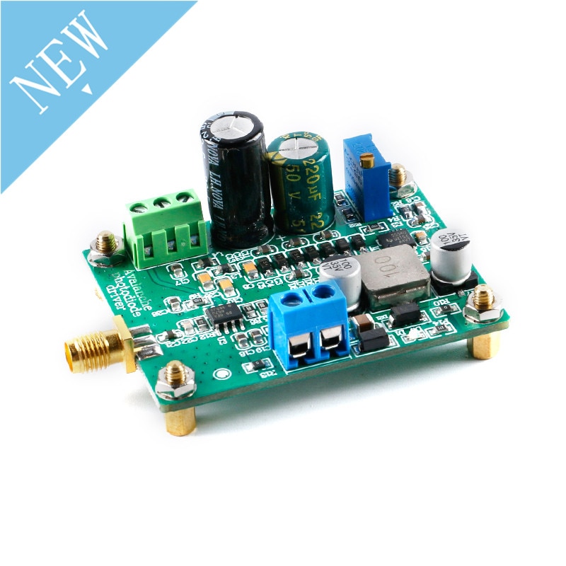
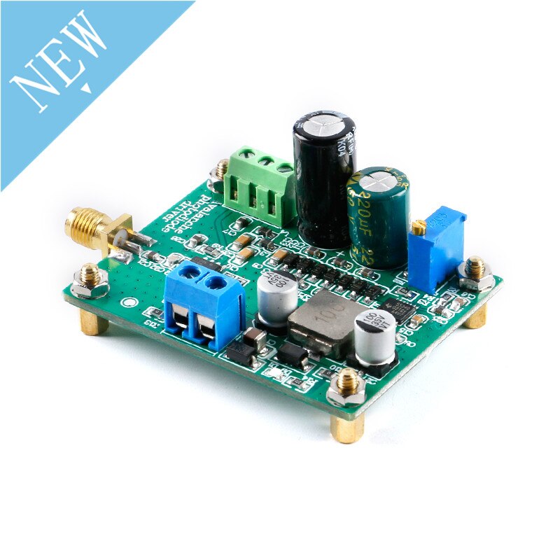
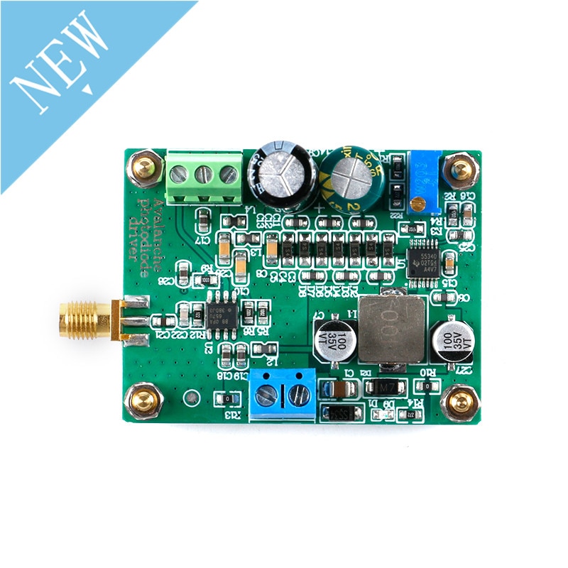
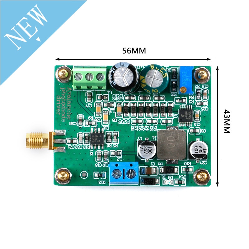
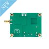
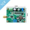
This module is a boost-type high-voltage module. The potentiometer on the board is to adjust the bias of avalanche diode. It is generally set to 100V when it leaves the factory. Do not over-adjust it, which will lead to avalanche diode or module damage. Modules need to use stable linear power supply, no surge and pulse, otherwise easy to damage the module.
Parameters:
Name: Photoelectric IV Converter Module
Power supply: 10V
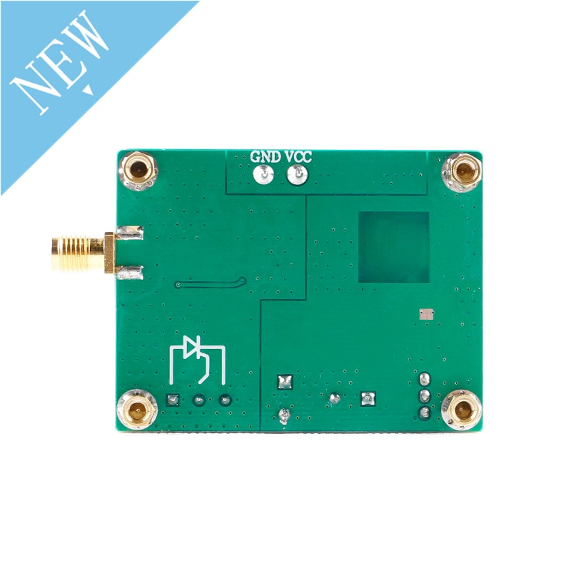
Size: (PCB) 56mm*43mm (positioning hole) 48mm*35mm
Signal input: receiving light signal by avalanche photodiode
Adjustment range of bias voltage of avalanche photodiode: 25V~175V
Bandwidth: 1KHz-150MHz (default configuration),DC~1KHz (customer self-configuration, C21 to 0 Euroresistance)

Specifications of our avalanche diodes:
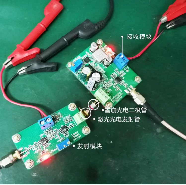
As shown in the connection test diagram, the two modules are all powered by 12V. The output end of the transmitting module transmits the optical signal to the avalanche photodiode connected with the input end of the receiving module with the laser photoemission tube.
Because the power of the selected laser emitter tube is small, the optical signal is not very concentrated, so the test distance must be relatively close to get a better effect.Of course, optical fiber can also be used for transmission, so the effect is ideal.
Transmitter module link with this module:\https://www.aliexpress.com/item/33003744073.html
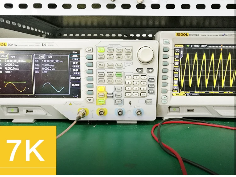
The signal generator inputs 7kHz to the transmitting module on the left, and the sine wave signal of 2Vpp passes through the electro-optic photoelectric conversion of two modules to get the effect picture of the oscilloscope on the right, with the frequency of 7.143khz
The signal generator inputs 1MHz to the transmitting module on the left, and the sine wave signal of 2Vpp passes through the electro-optic photoelectric conversion of two modules to get the effect picture of the oscilloscope on the right, with the frequency of 985.2KHz
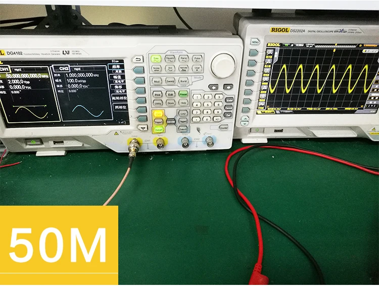
On the left side, the signal generator inputs 50MHz to the transmitting module, and the sine wave signal of 2Vpp is converted through the electro-optical photoelectric conversion of two modules to get the effect picture of the oscilloscope on the right side, with the frequency of 49.75MHz
The signal generator inputs 70MHz to the transmitting module on the left side, and the sine wave signal of 2Vpp is converted into electro-optic and electro-optic signals of two modules to get the effect picture of the oscilloscope on the right side, with the frequency of 69.93MHz
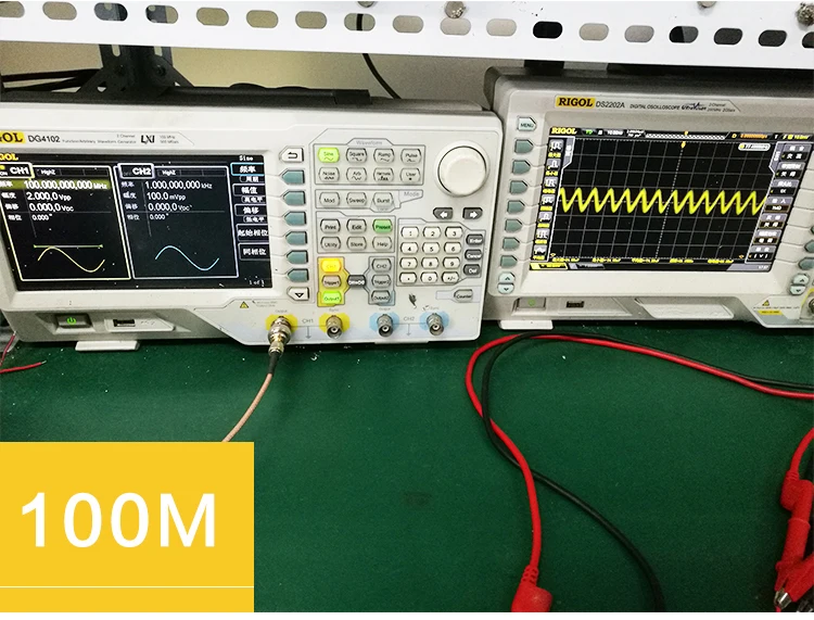
The signal generator inputs 100MHz to the transmitting module on the left, and the sine wave signal of 2vp is converted through the electro-optical photoelectric conversion of two modules to get the effect diagram of the oscilloscope on the right, with the frequency of 96.15MHz







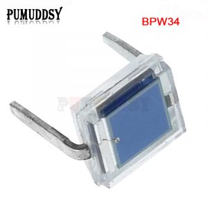 5pcs/lot Photodiode BPW34 New Original
Reviews
There are no reviews yet.